


More Information on High Power Pin and Sleeve Devices
While most products use standard plugs for power entry, high power devices can provide power to products that draw more than the rated output of common plugs and sockets. High power connectors can be made to specific national standards, but are not good choices unless sales are limited to a few markets. IEC 60309 defines a family of cable-mount connectors, plugs, and wall-mount inlets and outlets that can be used on equipment for both domestic and international markets. With these devices, it is not necessary to stock connectors for every national standard.
High power connection devices are used in applications where high power connection needs include detachability, security, and protection. Industries that may use high powered connection devices are those that require higher amperage and voltage than found in the normal circuit of a building. These industries include, but are not exclusive to: construction, which includes providing a power source connection for equipment and lighting; food service by connecting heating units, cookers, fryers, and warmers; providing power to vendor carts at fairs, shows, and booths; the entertainment industry for providing power for lighting, sound, camera video displays, and movements of props; and the computer industry to connect large computers, servers, and main frames.
More and more, power-hungry equipment is smaller in size and mobile. Users can wheel equipment that was once stationary to individual work stations or to where needed on a work site and simply plug it in. This mobility extends the productivity of users by giving them sole control over more powerful equipment. It also increases equipment usage, thus giving customers a great return on investment. Flexibility can give a customer a competitive edge.
When designing stationary equipment, panel-mount plugs and connectors are an option. The product can be used on the basis of how easily it can be installed. Wiring instructions and specifications for the mating outlet can be sent ahead of time so when the mating connector arrives, it can simply be plugged in and equipment powered up.
Interpower offers high power pin and sleeve devices that are 16/20A and 30/32A.
Features of the High Power Pin and Sleeve Devices (IEC 60309s)
Shells are Made of Impact-Resistant Plastic
The only metallic parts are the contacts themselves and the fasteners used to hold the various pieces of the plug and socket together. Plastic offers important safety advantages over metal in connector shells. If a current-carrying wire somehow works loose from its contact, a person handling a metal connector could get a lethal shock. A person is better protected from such a shock with a correctly assembled plastic connector.
The System Has Been Designed to Avoid Mismating
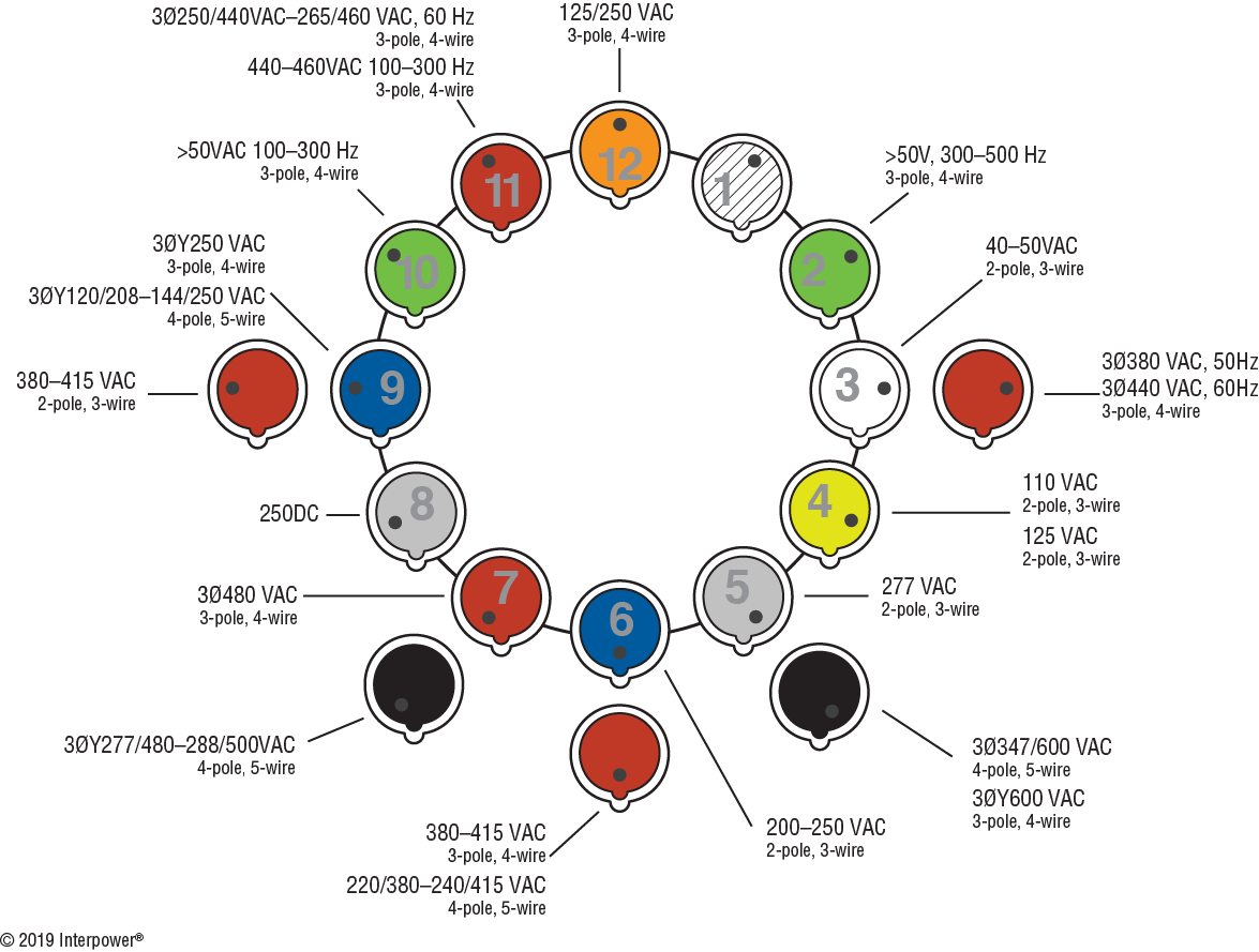
The system was designed to ensure polarity and avoid mismating of connectors. Polarity is ensured with a polarizing key and keyway and the diameter of the ground contact is greater than that of the other contacts. This ensures proper connection between the ground pins. External keyways ensure the correct alignment of contact pins. A keyway is like a key hole in a door which allows the key to enter only one way. The positions of the ground pins are relative to the socket’s key and are designated as a clock hour position depending on the voltage rating of the part. The clock position for plugs and inlets is a mirror image for the mating connectors and outlets. The chart below shows the color codes and hour designations. The keyway is positioned at six o’clock and the black dot indicates where the ground pin is located. For example, in the orange configuration, the ground pin is at the twelve o’clock position and the keyway is at the six o’clock position.
| Rated Voltage | Color 1, 2 |
|---|---|
| 40V–50V | |
| >50V | |
| 110V–130V | |
| 125V/250V | |
| 200V–250V | |
| 277V | |
| 380V–480V | |
| 500V–690V | |
|
|
Color-Coded Shells Made the Voltage Ranges Obvious
The high power pin and sleeve devices are color coded according to voltage. For easy identification, the products with the same voltage ratings are always the same color. The product’s color coding also helps to provide positive voltage and frequency matching. Additionally, this system features a series of graduated connector sizes indicating the current rating and number of contacts. The voltage rating is related to the location of the ground pin on the female device and the number of conductors.
| International | |||||
|---|---|---|---|---|---|
| 4 hour | 6 hour | 7 hour | 9 hour | 12 hour | |
| 3 wire |  110–130 |
 220–250 |
|||
4 wire |
 380–415 |
 200–250 |
|||
5 wire |
 200/346–240/415 |
 120/208–144/250 |
|||
| North America | |||||
|---|---|---|---|---|---|
| 4 hour | 6 hour | 7 hour | 9 hour | 12 hour | |
| 3 wire | 125 |
250 |
|||
4 wire |
 480 three-phase |
250 three-phase |
 125/250 |
||
| 5 wire |  277/480 three-phase |
120/208 three-phase |
|||
| Color & Rated Operating Voltage | |||
|---|---|---|---|
| Color | International | North America | |
| Yellow |  |
100–130 | 125 |
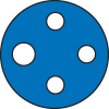
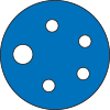
| Blue |  |
200–250 | 250 |
| Red |  |
380–480 | 480 |
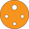
| Orange |  |
— | 125/250 |
Sockets Feature Hinged, Spring-Loaded Covers
IEC 60309 connectors and socket outlets feature hinged, spring-loaded covers which snap into place when the plug is removed. This reduces the risk that foreign objects will be inserted into the contacts. The hinged cover also serves as a locking mechanism to assure that once the plug and socket are mated they will not be accidentally uncoupled.
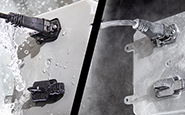
Models Come with Seals that Control the Intrusion of Moisture
Products in this family incorporate sealing mechanisms which control the intrusion of moisture and solid objects. This is protected in an ingress protection or more commonly known as an IP rating, which is derived from the IEC 60529. Products are typically rated IP 44 or IP 67. An IP rating of 44 means the product is protected against solid foreign objects greater than 1mm in diameter and against splashed water. If a product has an IP rating of 67, it is dust-tight and has protection against temporary immersion in liquids. IP 67 devices utilize a locking ring and collar assembly on mating devices to ensure attachment and maintain the IP rating.
| Symbol | IP Rating | Sealing Effectiveness |
|---|---|---|
| IP 44 | Splash Resistant Solid Objects > 1.0mm in Dia. |
|
| IP 67 | Water Tight, Splashproof Dust Tight |
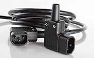
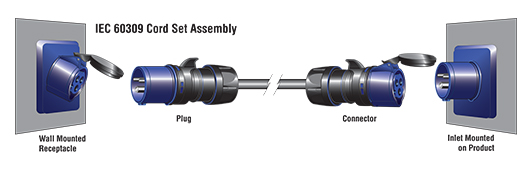
High Power Pin and Sleeve Device Cord Set Assembly
This cord set is terminated with a male and female connector on opposite ends of the cord. The user must have the correct socket wired into the branch circuit near the installation site and the equipment must be fitted with the mating male inlet. The components of this system make this an expensive solution, although it may save a customer some expense for electrical installation.
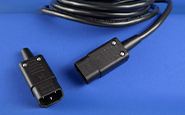
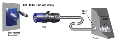
High Power Pin and Sleeve Device Cord Assembly
The power cord is terminated with a plug on one end and stripped conductors on the other. The conductors can be prepared to meet the requirements for attachment to a customer’s equipment. The customer must have the correct socket wired into the branch circuit near the installation site. This solution is less expensive than a cord set, but in mobile installations, a power cord can be awkward and possibly hazardous when the equipment is moved.
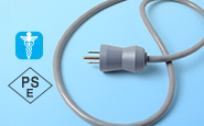
High Power Pin and Sleeve Device Connector Cord
Connector cords have a female connector on one end and stripped conductors on the other. The termination options are the same as those available for power cords. These cords would be permanently wired to a junction box by an electrician at the customer’s site. The equipment must be fitted with a mating male inlet connector.

Cord Test Procedures
High power pin and sleeve device assemblies are tested as follows:
- Correct polarity, correct continuity, absence of opens, absence of shorts.
- 25A ground integrity test for a duration of 1.5 seconds.
- Dielectric strength test of 2500VAC for at least one second between every combination of conductor pairs.
Pilot Pins and Contacts
Pilot pins and contacts are included with many of the higher current carrying IEC 60309 connectors for use in electrical interlock systems. These systems ensure power is safely disconnected before the plug and connector are disengaged. The pilot pin and contact disconnect before all other connections in the IEC 60309, and when wired to an electrical interlock, this disconnect signals the electrical interlock to shut off power.