


More Information on Connector Locks
Tool-Free Interpower Connector Locks | Locking-Screw Connector Locks
Connector locks secure cordsets to IEC 60320 power inlets to prevent accidental power interruption. Cordsets can be easily removed without disrupting the connector lock. Each cordset connector lock is designed for the molding of a specific cordset connector style. The connector locks can be used only with the screw-mounted power inlets.
Tool-Free Interpower Connector Locks
The Interpower connector lock has a wide array of industry uses. This design is available in two different sizes and does not require tools for use.
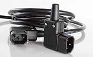
These connector locks can retain Interpower’s IEC 60320 C13/C14 and Sheet E/Sheet F combinations. While built specifically for Interpower connectors, including angled models, the Interpower Connector Lock may also secure a variety of other brands.
For C13/C14 Combinations
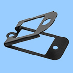 |
For use with Interpower IEC 60320 C13 connector molds 052, 053, 055, 056, and 057. For North American and international applications. |
 |
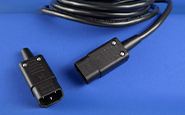
For Sheet E/Sheet F Combinations
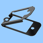 |
For use with Interpower IEC 60320 Sheet E connector mold E02. For North American and international applications. |
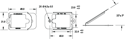 |
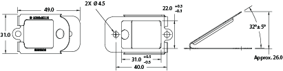
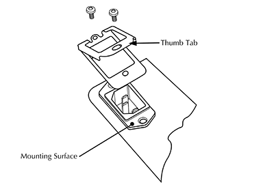
To Install Connector Lock
- Remove the two mounting screws of the inlet or outlet.
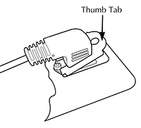
- Place connector lock on inlet, aligning the hole to the mounting holes with the
thumb tab pointing away from mounting surface. - Reinstall mounting screws (M4 max) through the connector lock and inlet holes, and fasten to component.
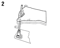
To Insert and Remove Connector
 |
 |
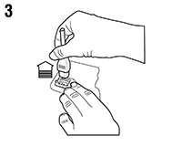 |
| Depress the thumb tab and fully insert the connector into the inlet or outlet. | Release the thumb tab which will automatically engage the lock, holding the connector in place. | To remove the connector, depress the thumb tab and hold down while extracting the connector from the inlet or outlet. |
Do’s and Don’ts
Interpower connector locks are manufactured to hold Interpower connectors firmly in place. They may also work with products from other companies. If needed, for connectors with a larger C13 body, it is suggested to use Interpower connector lock P/N 85910510; for connectors with a smaller Sheet E plug connector body, it is suggested to use Interpower connector lock P/N 85910500.
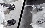
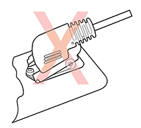
Note: If using angled connectors, orientate the thumb tab opposite of the cable exit direction.
Correct |
Incorrect |
 |
 |
Locking-Screw Connector Locks
 Assembly
Attach cord set connector lock to the inlet with mounting screws (specify a slightly longer mounting screw to accomodate the connector lock), then tighten the connector lock around cord set connector end by turning the captive screw on the connector lock. Connector end can be removed by loosening the screw on the lock without affecting the inlet and connector lock mounting.
For Cord Sets Rated 10/15A
 For use with Interpower IEC 60320 C13 connector molds 052, 053, 055, 056, and 057. For North American and international applications.

 For use with Interpower Sheet E plug mold E02. For North American and international applications.

For Cord Sets Rated 16/20A
 For use with Interpower IEC 60320 C19 connector molds 068, 069, 070, 013, and 015. For North American and international applications.

 For use with Interpower Sheet I plug mold 050. For North American and international applications.

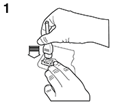
Installation Instructions
- To ensure proper alignment of the clamp with the connector, loosen the two mounting screws on the sides of the power inlet.
- Slip the connector lock under the mounting screws and leave the mounting screws loose.
- Insert the cord set through the connector lock into the inlet. Be sure that it is pushed completely into the inlet. This step is very important for your safety—a partially mated connector could cause a fire. Once the connector has been properly seated, the connector lock will keep it there in the future and help ensure your safety.
- Tighten the locking screw on the connector lock so that the clamp firmly grips the connector on the cord set.
- Tighten the two mounting screws on the sides of the inlet. The connector lock is now secured on the connector, so that cord sets may be easily removed and inserted in the future.
Locking the Cord Set
Note: After the installation has been done once, it is not necessary to adjust the side mounting screws again.
- Insert the cord set through the lock into the connector. Be sure that it is pushed completely into the connector.
- Tighten the locking screw on the cord set connector lock so that the lock firmly grips the cord set.
Removing the Cord Set
 Note: After the installation has been done once, it is not necessary to adjust the side mounting screws again.
- Loosen the locking screw on the cord set connector lock.
- Remove the cord set.
